

Care Centre Installation Requirements

In order to avoid any confusion or misinterpretation the following document has been drawn up. The primary objective of the document is to establish standards that all BeSecure Frail-Care installations comply with.
Standards allow for quicker installation time and faster fast turnaround on fault finding. BeSecure will sign off all completed installations based on the standards listed in this document.
Tools Required
Ladder
Brother label machine or similar
Extension cord
Masonry drill and bits
6mm masonry drill bit
4 mm plastic drill bits
20mm hole saw
Flat and Phillips screw driver
Terminal screw driver (<2mm flat blade)
Wire strippers
Ferrules & crimper
Heat shrink (6mm, 4mm & 2mm)
Heat gun
Cable markers
4 x 12mm nut and bolts
Fisher 6mm masonry wall screw
24mm & 26mm sockets or spanners (for the IP66 glands)
Pencil & tape measure
BeSecure Sniffer
Laptop with the BeSecure Utilities installed
Standard installation Practice
The following are installation best practices that need to be followed.
All devices are mounted at right angles using a spirit level
All installed cables must be labelled at both sides of the cable
When installed in false ceilings, BeSecure hardware must be installed in a hinged IP66 housing.
Wiring Specification
Description | Connected From | Connected To | Spec | |
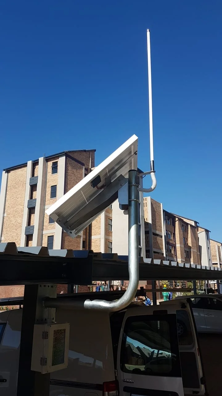
Solar Power Cable | Solar panel | Repeater | 18 AWG, 2 core, stranded copper conductors. (Belden 27916A or similar) | +V = Red Gnd = Black |
RS485 Comms | Repeater | Controller | 28 AWG, 2 pairs, stranded copper conductors, shielded, (Belden 8132 or similar) | A = Yellow B = Green Gnd = Black |
Input Comms | Bedside Unit | Ward Controller | 28 AWG, 2 pairs, stranded copper conductors, shielded, (Belden 8132 or similar) | Data 1 = Blue Data 0 = Orange |
Wiring Requirements
Only specified cable or a direct replacement from an alternative vendor must be used.
All cable ends must have the following:
Heat shrink
Ferrules
Cable markers as per the assigned number for that cable
All unused cable must be cut away
Where multiple cable cores are used for a single connection the cables must be twisted together with a ferrule connecting both at the end.
Bed numbering
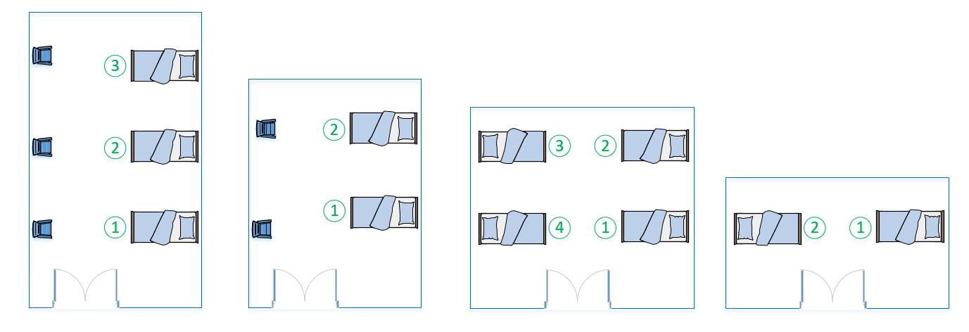
Ward bed numbering is standardized. The numbering model is as follows:
While standing at the ward main door the first bed on your right is number 1
The second bed on the right is number 2
This continues until all the bed on the right are numbers
The furthest bed on the left is the next number, counting up as you come back to the main door.
The images below give examples of the various bed layouts and the associated numbering.
The full unique number allocated to the bed will be the Ward number first then a dash and then the bed number. For example, bed number 2 in ward 1 will be 01-02; Bed number 4 in ward 8 will be 08-04.
All Bedside Units (BHI1003-051-01) must be labelled internally (label on the lid and the base) with this labelling format.
Port Connections
Ward | Bed | Label (Cable & PCB) | Ward Controller Port |
01 | 01 | 01-01 | 01 |
01 | 02 | 01-02 | 02 |
01 | 03 | 01-03 | 03 |
01 | 04 | 01-04 | 04 |
02 | 01 | 02-01 | 01 |
02 | 02 | 02-02 | 02 |
02 | 03 | 02-03 | 03 |
02 | 04 | 02-04 | 04 |
The bed numbering corresponds with the ports on the Ward Controller. The table below provides the format that must be followed. The pattern shown is then followed out to additional rooms.
Ward Controllers Architecture
Each ward will have a Ward Controller installed above the main entrance to that ward. The following installation requirements apply:
The Ward Controller (BHI1003-050-01) will communicate with the BeSecure Repeaters via the BeSecure 868Mhz Wireless network.
The Ward Controller can support a maximum of 4 Bedside bell-press units (BHI1003-051-01)
The maximum distance from the Ward Controller to the Bedside Unit must not exceed 50m
The Ward Controller must be powered locally using the supplied power supply unit.
The Bedside Units are powered from the Ward Controller.
The Beside Units must be connected to the Port number allocated to that respective bed. The numbering chart can be reviewed in the Bed Numbering section of this page.s labelling format.
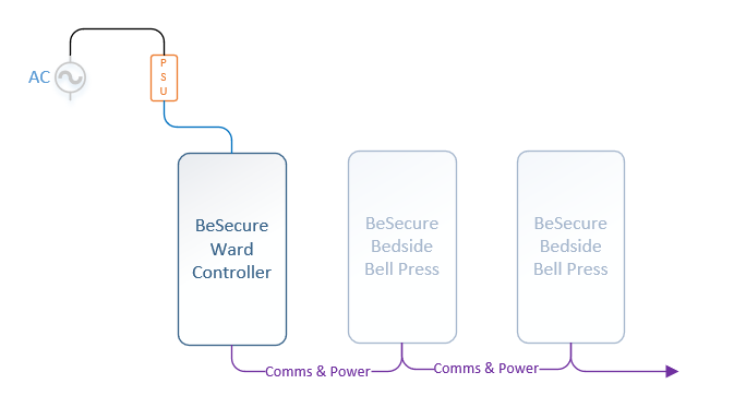
Figure 1 - Ward Controller connection to the Bedside Units
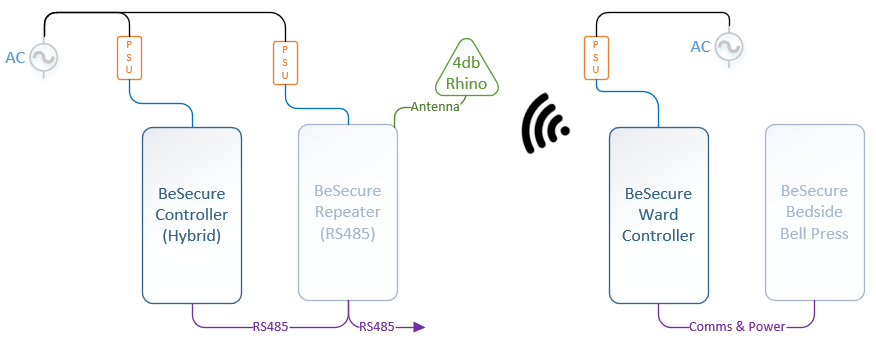
Figure 2 - Ward Controller to Repeater Connection
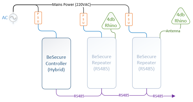
RS485 Architecture
Frail care installations are completed with RS485 Repeaters. As per the system architecture below the following installation requirements apply:
The RS485 cable must be installed as a daisy chain connection
The maximum distance from the Controller to the final Repeater must not exceed 500m
The total number of Repeaters on a single RS485 bus must not exceed 7
The Controller and Repeaters must be powered at their installed location using the supplied Power Supply Unit (PSU)
All BeSecure Repeaters and Controller must be installed in IP66 housing if installed in the false ceiling or cupboard.
A | Yellow |
B | Green |
Gnd | Black |
Installation Notes
All BeSecure Repeaters and Controller in the field must be installed in the same way. This will reduce support efforts in tracing and establishing faults in the unlikely event that they arise.
When establishing a location of the hardware the following considerations should be taken into account:
The BeSecure Controller or Repeater is easily accessible.
Ideally without a ladder however If a ladder is necessary the unit must be close to a roof access point.
The mounting point should consider the need to place a laptop next to the housing when period firmware upgrades need to be made.
Enough cable slack must be allowed to ensure that the cables are not under tension and there is some give in the housing should items need to be moved around.
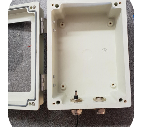
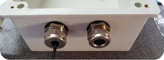
Enclosure Installation Guidelines
Install the two metal glands
20mm from the lip
50mm in from each side
Left gland is a 00
Right gland is 01
The wiring is as follows:
Left (Gland size 00)– PSU and comms from Controller
Right (Gland size 01) – Antenna and comms to next Repeater
Enclosure Installation
Enclosure Installation
Wiring Guidelines
Push the wire from the Controller through the left gland
Push the wire from the next Repeater through the right gland
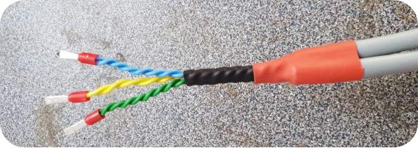
Strip back the sheath 80mm
Twist the wires together and strip the ends
Locate a ferrule on each
Cover with heat shrink and shrinkund.
Wiring Steps
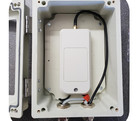
Preparing the Peripheral Enclosure
Mount the BeSecure base onto the IP66 housing base
The top of the base should be 5mm below the backing plate line
Drill a 4mm hole in the top right and left corners of the base and through the mounting plate
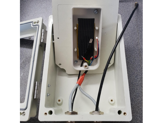
Insert the PSU and comms cables into the base cabling holes and insert the gland clips.
Fasten the base to the mounting plate.
Insert the antenna cable through the right gland
Peripheral Enclosure Mounting
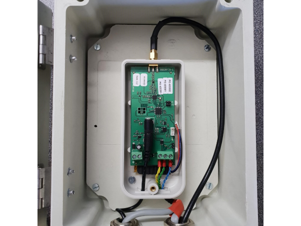
Connecting the Peripheral PCB
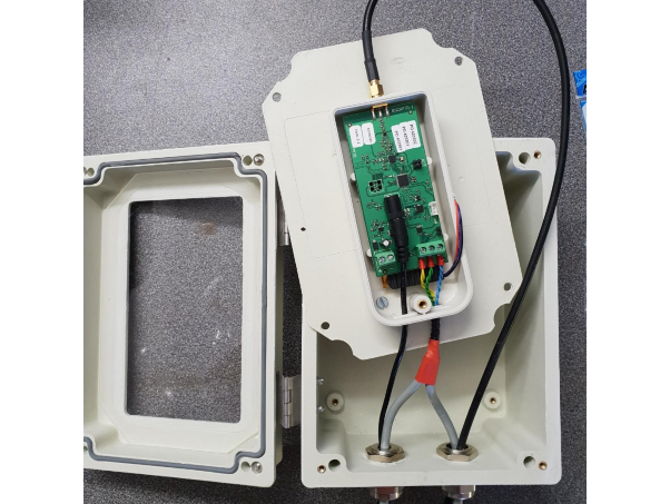
Connect the Repeater PCB
Insert the PCB and connect the PSU
Wire up the RS485 Communications
A = Yellow
B = Green
Gnd = Blue
Connect the rubber grommet and Antenna on the top connector
Connecting the Peripheral PCB
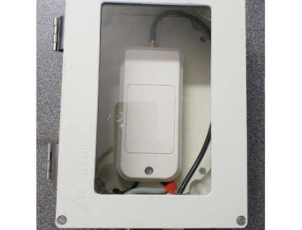
Mounting the Peripheral into the main enclosure housing
Insert the mounting plate into the housing
Print and mount required labels to the mounting plate (not shown in this image)
Locate the mounting plate
Fasten all 4 mounting points of the mounting plate
Neaten cables
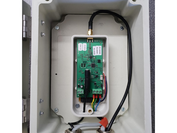
Mounted Repeater
Powering up the Equipment
Power up and commission
Once all hardware has been installed
Ensure the serial number is programmed in the software
Upload the modified Config file
Bring up each Repeater (Mains power and battery connected) and watch on the sniffer to ensure that the communications are as to be expected.
Close up the BeSecure lid
Close up the IP66 lid
Ensure that the label for that Repeater is visible on the lid of the housing (not shown here)
Complete Repeater, ready for deployment
Sealed Repeater, Complete. Ready for Deoployment
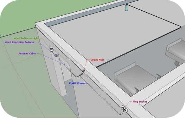
Installation Guide Diagram 1
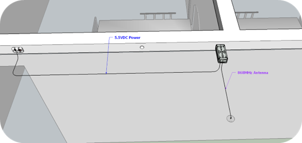
Installation Guide Diagram 2