

BLE Controller Installation

In order to avoid any confusion or misinterpretation the following document has been drawn up. The primary objective of the document is to establish standards that all installations comply with.
Standards allow for quicker installation time and faster fast turnaround on fault finding. OneSpace will sign off all completed installations based on the standards listed on this page.
Wiring Requirements
Only specified cable or a direct replacement from an alternative vendor must be used
All cable ends must have the following:
Ferrules
Cable markers as per the assigned number for that cable
All unused cable must be cut away
Where multiple cable cores are used for a single connection the cables must be twisted together with a ferrule connecting both at the end.
Hardware & Board Description
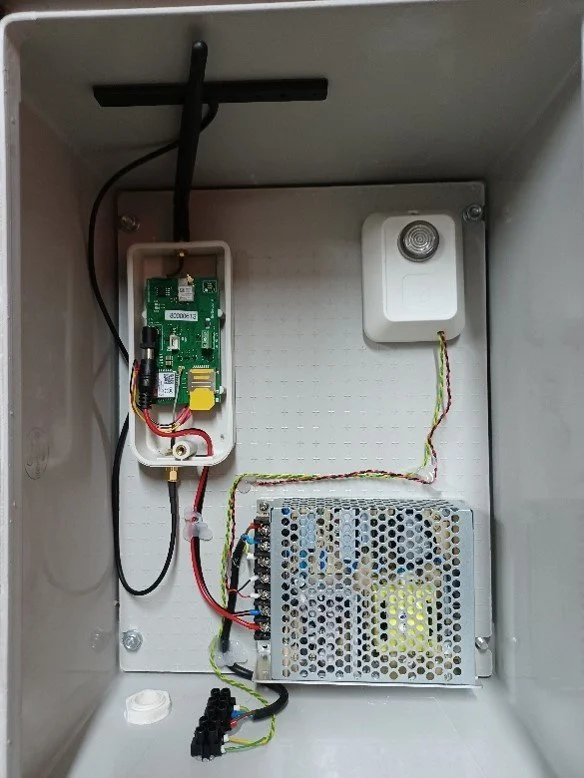
BLE Controller Housing
Hardware
Power Supply – MeanWell 12/5 Vdc plus Ground Loop on the 12V
Cable – Mylar 2 pair twisted
Ground Loop - Input 12V – Red/ Neg – Black , Output 12 V - Orange / Neg - Brown
BLE Controller – 5Vdc
Wiegand Host (RS485) – 12Vdc
Mains – 220v AC – onto connector block – L/N/E
RS485 out Connector Block - Cable Colour Code Yellow – A / Green – B
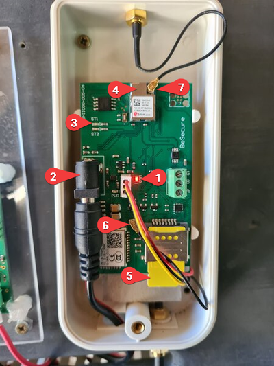
BLE Controller
Board
Battery Power Indicator
12V DC Port..
ST1 Controller Polling Light.
BLE Adapter
GSM SIM Slots. This can house 2 Sims.
GSM Antenna Output.
BLE Antenna Output
Installation
Location
Central to the gates in a secure position away from any WiFi – routers or any other high frequency equipment
Wall Mounting
Use external brackets supplied with the casing fitted at each corner. Fasteners – 6mm /75mm nylon wall anchors
Power
Switchable 220 Vac power wall socket
RS485
Mylar 4pair twisted – maximum length of 500m
Connect the RS485 cable to the downstream devices using the daisy chain method.
Label the RS485 cable on each device with “From device” and “To” device.
Configuration
SIM Card Installation
Confirm that SIM cards are installed correctly – Vodacom as primary (top connector)
GSM Antenna
Ensure connected correctly and secured to the inside away from the power supply
BLE Antenna
Ensure that the BLE antenna is connected securely
Tools Required & Start Up
Tools Required
Ladder
Headlamp
Brother label machine or similar
Extension cord
Drill
Masonry drill and bits
6mm masonry
4mm all purpose drill bits
Flat and Phillips screw driver
Terminal screw driver (<2mm flat blade)
Wire strippers
Ferrules & crimper
Heat shrink (6mm, 4mm & 2mm)
4 x 12mm nut and bolts
6mm masonry wall screw
24mm & 26mm sockets or spanners (for the IP66 glands)
Pencil & tape measure
Laptop with the BeSecure Login
GSM internet connection for the laptop
Start Up
Connect battery to Controller and then switch on Main 220vac
Power supply Test – Measure the 12Vdc and 5Vdc output from power supply
LED Status – when controller is on line and connected
GSM LED
Flashes 1 x every 2 sec when establishing a connection
Flashes 2 x per second when connected to the network
Status 1 LED (ST1 LED)
Flashes 1 x per second when connected to the cloud App.
Power LED
On solid when the battery is charging