

BLE/MFP Gateway Installation

In order to avoid any confusion or misinterpretation the following document has been drawn up. The primary objective of the document is to establish standards that all installations comply with.
Standards allow for quicker installation time and faster fast turnaround on fault finding. OneSpace will sign off all completed installations based on the standards listed on this page.
Cable Run
The cable run is an important part of the installation. To ensure long term stability of the location it is imperative that the integrity of the cable is a primary focus during installation.
In particular, the following should be considered.
As far as possible the cable should be protected against direct contact with UV from the sun.
The cable should have no friction points on its complete run. In particular the cable should not be run over or near any physical feature that moves or is possibly prone to moving to avoid friction points over time.
If there is a concern or questions relating to the integrity or location of the cable it must be re-run. The cost of a call out later far exceeds the cost of the re-run.
Wiring Requirements
Only specified cable or a direct replacement from an alternative vendor must be used
All cable ends must have the following:
Ferrules
Cable markers as per the assigned number for that cable
All unused cable must be cut away
Where multiple cable cores are used for a single connection the cables must be twisted together with a ferrule connecting both at the end.
Hardware
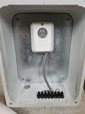
IP65 Case with MFP PCB – BHI 1003-030-02
Connector Block consists of the following
12Vdc – Red
Gnd - Black
A - Yellow
B - Green
Com Relay – Brown
N/O - Purple
N/C - Blue
Cable Types
RS485 - Mylar 4 pair twisted
Power – Red/Black rip cord
Relay – white rip cord – boom gate trigger
Installation
Location / BLE range
The BLE gateway has a line of sight range of 7m to the Controller. However if the BLE Gateway is not in sight of the controller then the Gateway must be installed as close to the controller as possible, but still be in range for the access devices to connect via BLE to the gateway which has a range of 10m.
Mounting
Open the IP 65 case and remove the component panel. If not already done drill 4 x 6mm holes at each corner of the casing for the mounting screws. Fasten the casing to the surface with suitable screws. Re fit the component panel.
Power
Connect the Independent 12Vdc to the connector block.
RS485
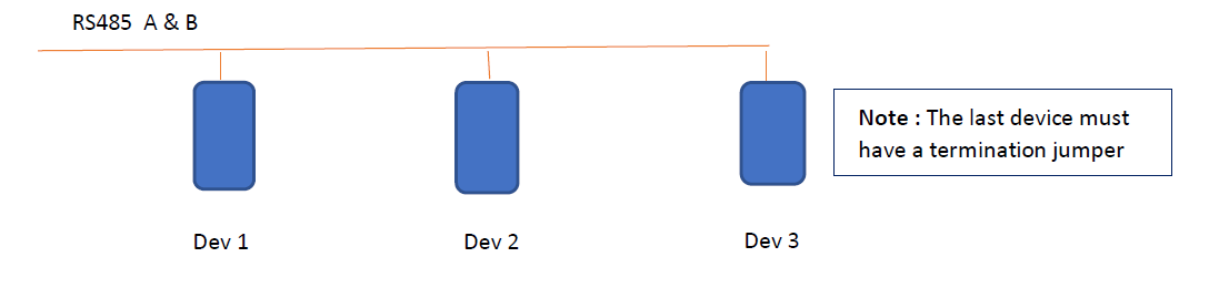
If the gateway is configured for RS485 connect the Yellow and Green to the A & B connectors on the block in a daisy chain method. That is, there will be an incoming Yellow and Green and if this device is not the last device then there will be a outgoing Yellow and Green to connect to the next device. See diagram below.
Relay
Connect the Relay trigger cable to the Com and N/O connectors on the block
RS485 Configuration
Jumper settings
The BLE/MFP gateway has a set of 3 Jumpers close together and 1 set of jumpers loacted near the gateway's relay switch.
The set of 3 jumpers is used to configure the device ID/Address for RS485 configured devices.
On the BLE/MFP Board there is a lone jumper near the relay switch. This is where the termination Jumper needs to be set if the device is the last peripheral in the RS485 Bus line.
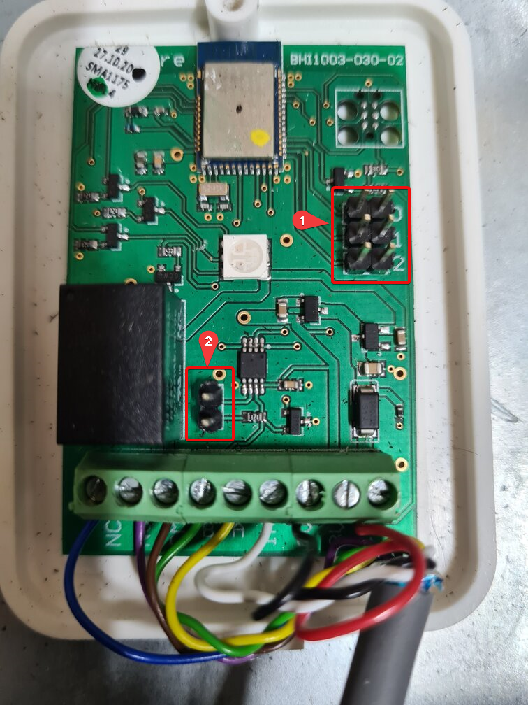
Jumper Locations
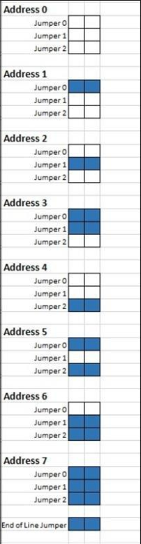
List of configurable RS485 Addresses
Important Note: ONLY the RS485 Host Device and the LAST device on its RS485 Line needs to have termination Jumpers installed. The RS485 Host will come with it's termination jumper pre-installed.
Tools Required & Start Up
Tools Required
Ladder
Headlamp
Brother label machine or similar
Extension cord
Drill
Masonry drill and bits
6mm masonry
4mm all purpose drill bits
Flat and Phillips screw driver
Terminal screw driver (<2mm flat blade)
Wire strippers
Ferrules & crimper
Heat shrink (6mm, 4mm & 2mm)
4 x 12mm nut and bolts
6mm masonry wall screw
24mm & 26mm sockets or spanners (for the IP66 glands)
Pencil & tape measure
Laptop with the BeSecure Login
GSM internet connection for the laptop
Start Up
Power on the device
Measure the 12 Vdc supply and if not within the 5% tolerance replace
LED Status
The LED on the gateway will be a light blue on start up
If the device is configured in BLE mode It will change to a solid purple when connected to the controller
If configured in RS485 the LED will flash purple when connected to the controller